Common 3D printing issues & design guidelines
3D printing offers unparalleled versatility in manufacturing, although it also presents specific challenges. Follow these tips to achieve the best outcomes from your prints.
3D printing offers unparalleled versatility in manufacturing, although it also presents specific challenges. Follow these tips to achieve the best outcomes from your prints.
We know our 3D printers inside out. Over the years, we’ve learnt what works, what to avoid, and how to get the most out of this innovative technology. We’ve distilled over a decade of experience into this simple guide to help you design the optimal 3D model for a successful print.
Please confirm your files meet these guidelines to ensure you get a result you are happy with. If your model doesn’t comply, it might limit our capacity to work with it. We can attempt to print certain non-compliant models to the best of our ability, but be aware that outcomes may vary.
If you are unsatisfied with your final parts, you must contact us within 5 days of receiving the delivery. Please note we are unable to refund orders that do not adhere to the design guide.
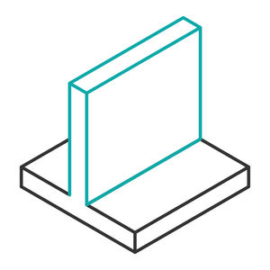
Maintain a wall thickness of at least 0.8 mm. Anything thinner might fail to print or could break easily. For enhanced strength, consider a wall thickness between 2-3 mm.
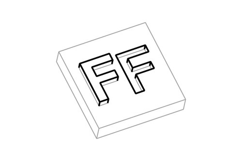
Text should have a consistent stroke thickness of at least 0.8 mm. Use a minimum 0.5 mm line width for engraved details and 0.9 mm for embossed detail. Aim for a height of 2 mm on these details to ensure visibility.
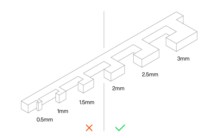
To ensure the printed object retains its form, a minimum feature size of 2 mm is advisable. This allows the plastic to solidify properly and maintain its intended shape.
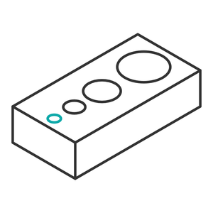
If your design includes dimensioned holes for screws, bolts, or bearings etc. they should be at least 2 mm in diameter to ensure proper resolution. For maximum accuracy, model the holes slightly smaller and drill in after printing.
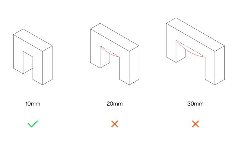
Bridging means printing in the air between two points of the same height, without needing support material. Avoid adding gaps or bridges of over 15 mm to prevent sagging.
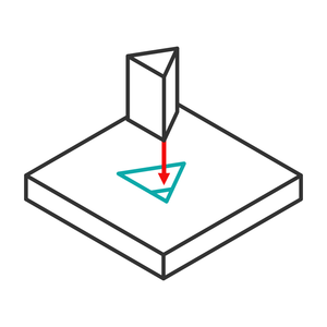
For 3D-printed parts intended to fit together, a clearance of approximately 0.3 mm is recommended for a loose fit and about 0.15 mm for a tighter fit.
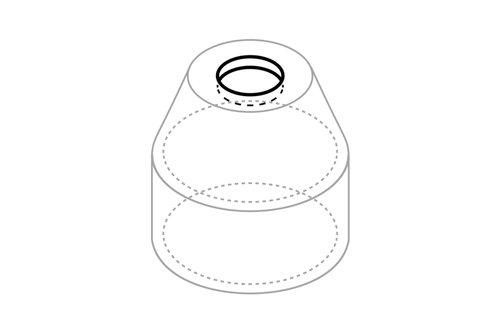
Be aware that hollow prints will require a wide opening for us to clean out any internal support material – otherwise our tools won’t fit inside. For example, a bottle with a narrow top would be inaccessible. We suggest an opening diameter of at least 40-50 mm.
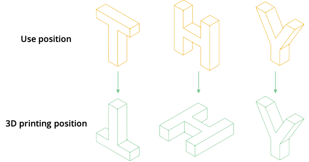
When preparing to manufacture your order, we will choose the orientation that will produce the best quality print. The ideal orientation will depend on the geometry of your model, overhangs, and necessary support material among other factors.
Our CAD engineers can use specialist software to adjust your file for 3D printing. Email your model to info@surfacescan.co.uk and we’ll let you know if this is necessary and provide a quote.
Due to infinitesimal details such as hair or capes, small figurines or tabletop pieces for games like Warhammer can be difficult. If the model doesn’t adhere to the design guide above, certain features may fail to print, lack structural integrity, or be poor quality. In these cases, resin 3D printing could be a better option.
Models with steep curves, sharp angles, or intricate details on a vertical axis are prone to stair-stepping in 3D printing. Examples include architectural models with intricate facades and objects with spiral or helical features. These models display the “staircase” effect more prominently due to the layer-by-layer construction method of 3D printing.
Each 3D printing material has its own quirks that affect the process. For example, models that require support are not ideal for TPU, and ASA struggles with thin parts. If you are unsure what material would be suitable, feel free to email us your file and we can advise the best route.
Warping in 3D printing occurs when parts of a model curl away from the print bed, a common issue with larger or long parts, especially when using high-temperature materials like ASA. This problem arises because plastics generally shrink as they cool, leading to deformation and potential detachment from the print bed.
To mitigate warping, several strategies can be considered: using a heated bed to reduce shrinkage, adding rafts or brims to secure the print’s edges, employing a heated enclosure for even temperature, and disabling cooling fans to keep layers warm. These solutions collectively enhance adhesion and minimize the effects of cooling-induced shrinkage.
Under-extrusion in 3D printing is identified by thin layers or missing infill, indicating insufficient material deposition during the print process. This can stem from various issues, including clogged nozzles, incorrect filament diameter settings, low extruder temperature, or incorrect printing speed settings, leading to weak structures or incomplete prints.
Addressing under-extrusion involves ensuring the nozzle is clean and the filament is properly fed. Adjusting the printer settings, such as increasing the extruder temperature or calibrating the printer’s speed and flow rate, can also significantly improve print quality. These steps help maintain consistent material flow and achieve the desired print accuracy.
Over-extrusion in 3D printing manifests as excess material on the print, causing blobs, zits, or overly thick layers, which can detract from the model’s detail and accuracy. This issue often stems from incorrect slicer settings, such as too high extrusion multiplier or flow rate, incorrect filament diameter input, or excessive printing temperature.
To resolve over-extrusion, calibrate the extruder to ensure accurate material flow, adjust slicer settings for proper filament diameter and extrusion rates, and fine-tune the printing temperature to match the filament type. These adjustments help achieve a balanced extrusion, enhancing the print’s quality and fidelity.
Layer shifting in 3D printing is a problem where the layers of an object being printed do not align properly, leading to a misshapen final product. This issue is usually caused by the movement of the printer not being precise enough, which can be due to various mechanical reasons like loose belts, improper lubrication, or even the printer being jostled during operation.
To correct layer shifting, it’s crucial to ensure all mechanical parts are well-maintained, properly calibrated, and securely fastened. Reducing the printing speed can also help improve accuracy and prevent shifts. Ensuring the printer is on a stable surface and checking for any software updates that might improve performance are additional steps to take.
Layer separation, or delamination, occurs when the layers of a 3D print do not properly adhere to each other, resulting in splits or cracks within the object. This issue often arises from inadequate bed or extrusion temperatures that prevent layers from bonding effectively.
To prevent layer separation, ensuring optimal printing temperatures for both the bed and the extruder is crucial. Lowering print speed and ensuring layer height is 20% less than your nozzle diameter can also improve layer adhesion, as can using a printer with a heated build chamber for materials prone to delamination.
Stringing in 3D printing occurs when thin strands of plastic are left between parts of a print, caused by molten material oozing out of the nozzle while moving between sections. This is often due to excessive hot end temperature or incorrect retraction settings.
To minimize stringing, optimizing the printer’s retraction settings is key, including retraction speed and distance. Adjusting the printing temperature to the lowest possible value that still allows for good extrusion can also help, as well as enabling travel settings that avoid crossing open spaces.
Ringing, or ghosting, in 3D printing refers to the appearance of echoes or ripples around sharp corners, resulting from printer vibrations or rapid movements. This effect is typically caused by the inertia of the printer’s moving parts, leading to slight oscillations that are replicated in the print layers.
Reducing ghosting involves lowering the print speed to decrease vibrations, optimizing acceleration settings, and ensuring the printer’s mechanical components are tight and well-tuned. Enhancing the rigidity of the printer frame can also mitigate this issue by minimizing the amount of vibration transferred to the print.
When loading a model into slicing software, everything may look fine, but upon printing, some parts can end up stringy and messy due to overhangs. This issue arises because Fused Filament Fabrication (FFF) builds each layer upon the previous one, leading to problems if part of the model lacks underlying support, causing the filament to extrude into thin air.
Addressing messy overhangs involves several strategies: adding supports via slicing software, creating in-model supports for less intrusive support removal, designing a support platform for complex parts, angling walls to self-support, or breaking the model into separate prints to reorient overhangs into bases.
Transform physical items into precise digital models with our metrology-grade 3D scanners.
Use your own STL file or 3D scan data for one-off prints or batch production runs.
Convert your scan data into an editable CAD file, ready for the next stage of your project.
We’re ready for your enquiry. Please fill out the form, and someone will get back to you as soon as possible or give us a call, which ever suits you best.
This website uses cookies to ensure you get the best experience on our website.